
What's on the table?
Inspiration
I was recently discussing a design with a colleague in the industry. He was tasked with deciding on a platform for his Tier 3 access rings; These rings would be low bandwidth and potentially oversubscribed. The platform he decided on was the NCS500 series.
The main problem he was having was delivering full tables to clients connected to the T3 ring, as the NCS500 series routers could not handle full tables in FIB. They were also low scale in general – as also seen in the NCS55XX series – with 4k ECMP FEC entries limitation.
The solution he landed on was to introduce PWHE's (Pseudo Wire Head-ends) into his network; The NCS500 routers would act as a point-to-point l2vpn x-connect to the S-PE's (Switching PE, that terminates the PWHE's).
I listened to the main concern he had in mind: the ability to advertise full tables to customers. I proposed he consider a BGP table-policy instead. He wasn't fully convinced by the idea, so I've decided to lab it up to explore more and discover it's efficacy for myself.
Lab Topology
I've created the following topology to represent a Tier-1 ring with a Tier-3 ring attached:
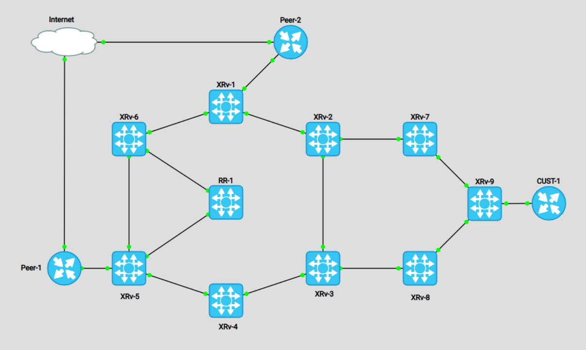
For the above topology, XRv-1 to 6 are our Tier 1 ring. They are acting as bigger routers, capable of holding full tables and multiple VPN services. Routers XRv-7 to 9 are the Tier 3 ring. These will act as our low scale NCS500 series routers. RR-1 is simply our IPv4 unicast route-reflector.
The two Peer routers are simply advertising EBGP prefixes to our border routers, for demonstrating the sub-optimal routing from XRv-9's perspective. I also setup a Customer CE router as an internet customer, to demonstrate it's view of the topology.
Configuring PWHE
Now it's time to build the proposed topology. The concept of a PWHE's was fairly new to me; Thus, I had to refer to documentation.
First we create our PWHE interface & matching L2VPN x-connect on XRv-3, acting as the S-PE. You can see that XRv-3 has an established BGP session with the CUST-1 router:
RP/0/0/CPU0:XRv-3#show run formal | i "PW|xconnect"

Building configuration...
interface PW-Ether100
interface PW-Ether100 ipv4 address 203.0.113.5 255.255.255.252
interface PW-Ether100 attach generic-interface-list gil1
l2vpn xconnect group pwhe
l2vpn xconnect group pwhe p2p xc_main_interface
l2vpn xconnect group pwhe p2p xc_main_interface interface PW-Ether100
l2vpn xconnect group pwhe p2p xc_main_interface neighbor ipv4 10.255.255.9 pw-id 100
RP/0/0/CPU0:XRv-3#
RP/0/0/CPU0:XRv-3#show bgp sessions

Neighbor        VRF                   Spk    AS   InQ  OutQ  NBRState     NSRState
10.255.255.10   default                 0  6275     0     0  Established  None
203.0.113.6     default                 0   789     0     0  Established  None
RP/0/0/CPU0:XRv-3#
RP/0/0/CPU0:XRv-3#show arp  | i "Add|PW-"

Address         Age        Hardware Addr   State      Type  Interface
203.0.113.5     -          0257.cc67.a402  Interface  ARPA  PW-Ether100
203.0.113.6     00:03:29   0c05.f335.0000  Dynamic    ARPA  PW-Ether100
RP/0/0/CPU0:XRv-3#
XRv-9 is delivering this connection purely via L2VPN x-connect:
RP/0/RP0/CPU0:XRv-9#show run l2vpn
l2vpn
 xconnect group pwhe
  p2p xc_main_intf
   interface GigabitEthernet0/0/0/2
   neighbor ipv4 10.255.255.3 pw-id 100
   !
  !
 !
!

RP/0/RP0/CPU0:XRv-9

RP/0/RP0/CPU0:XRv-9#show mpls ldp neighbor brief

Peer               GR  NSR  Up Time     Discovery   Addresses     Labels
                                        ipv4  ipv6  ipv4  ipv6  ipv4   ipv6
-----------------  --  ---  ----------  ----------  ----------  ------------
10.255.255.3:0     N   N    00:02:35    1     0     5     0     0      0

RP/0/RP0/CPU0:XRv-9#
RP/0/RP0/CPU0:XRv-9#show l2vpn xconnect pw-id 100
Legend: ST = State, UP = Up, DN = Down, AD = Admin Down, UR = Unresolved,
        SB = Standby, SR = Standby Ready, (PP) = Partially Programmed

XConnect                   Segment 1                       Segment 2
Group      Name       ST   Description            ST       Description            ST
------------------------   -----------------------------   -----------------------------
pwhe       xc_main_intf
                      UP   Gi0/0/0/2              UP       10.255.255.3    100    UP
----------------------------------------------------------------------------------------
RP/0/RP0/CPU0:XRv-9#

\\ The BGP Upstream peers are also learning the advertised prefix from the customer

kazaii@CUST-1:~$ show ip route connected

C>* 25.54.60.0/24 is directly connected, lo, 00:14:17
C>* 203.0.113.4/30 is directly connected, eth0, 00:14:17
kazaii@CUST-1:~$

kazaii@Peer-1:~$ show bgp ipv4 25.54.60.0 bestpath
BGP routing table entry for 25.54.60.0/24
Paths: (2 available, best #2, table default)
  Advertised to non peer-group peers:
  1.1.1.2 70.20.31.2
  6275 789
    1.1.1.2 from 1.1.1.2 (10.255.255.5)
      Origin incomplete, valid, external, best (AS Path)
      Last update: Tue Jul 26 00:17:58 2022
kazaii@Peer-1:~$
It's worth noting that the above configuration created the pseudowire via LDP signalling. You can, however, utilize EVPN-VPWS .. to keep this BGP signalled and less overhead.
The use of EVPN for VPWS eliminates the need for signaling single-segment and multi-segment PWs for point-to-point Ethernet services. You can also configure the PWHE interface and a bridge domain access pseudowire using EVPN-VPWS.
Customer View over PWHE
Finally, the Customer Router is able to reach the PWHE interface and is learning the full table
kazaii@CUST-1:~$ ping 203.0.113.5
PING 203.0.113.5 (203.0.113.5) 56(84) bytes of data.
64 bytes from 203.0.113.5: icmp_seq=1 ttl=255 time=2.31 ms
64 bytes from 203.0.113.5: icmp_seq=2 ttl=255 time=2.31 ms
64 bytes from 203.0.113.5: icmp_seq=3 ttl=255 time=1.85 ms
64 bytes from 203.0.113.5: icmp_seq=4 ttl=255 time=1.69 ms
^C
--- 203.0.113.5 ping statistics ---
4 packets transmitted, 4 received, 0% packet loss, time 8ms
rtt min/avg/max/mdev = 1.689/2.040/2.313/0.277 ms
kazaii@CUST-1:~$ show bgp summary

IPv4 Unicast Summary:
BGP router identifier 25.54.60.1, local AS number 789 vrf-id 0
BGP table version 16
RIB entries 31, using 5952 bytes of memory
Peers 1, using 21 KiB of memory

Neighbor        V         AS   MsgRcvd   MsgSent   TblVer  InQ OutQ  Up/Down State/PfxRcd   PfxSnt
203.0.113.5     4       6275         6         7        0    0    0 00:01:28           14       16

Total number of neighbors 1
kazaii@CUST-1:~$

kazaii@CUST-1:~$ show ip route bgp
Codes: K - kernel route, C - connected, S - static, R - RIP,
       O - OSPF, I - IS-IS, B - BGP, E - EIGRP, N - NHRP,
       T - Table, v - VNC, V - VNC-Direct, A - Babel, D - SHARP,
       F - PBR, f - OpenFabric,
       > - selected route, * - FIB route, q - queued, r - rejected, b - backup

B>* 1.1.1.0/30 [20/0] via 203.0.113.5, eth0, weight 1, 00:01:38
B>* 1.1.1.100/32 [20/0] via 203.0.113.5, eth0, weight 1, 00:01:38
B>* 2.2.2.0/30 [20/0] via 203.0.113.5, eth0, weight 1, 00:01:38
B>* 2.2.2.100/32 [20/0] via 203.0.113.5, eth0, weight 1, 00:01:38
B>* 8.8.8.0/24 [20/0] via 203.0.113.5, eth0, weight 1, 00:01:38
B>* 23.74.88.0/24 [20/0] via 203.0.113.5, eth0, weight 1, 00:01:38
B>* 50.50.50.0/24 [20/0] via 203.0.113.5, eth0, weight 1, 00:01:38
B>* 60.60.60.0/24 [20/0] via 203.0.113.5, eth0, weight 1, 00:01:38
B>* 66.77.230.0/24 [20/0] via 203.0.113.5, eth0, weight 1, 00:01:38
B>* 70.20.31.0/30 [20/0] via 203.0.113.5, eth0, weight 1, 00:01:38
B>* 70.70.70.0/24 [20/0] via 203.0.113.5, eth0, weight 1, 00:01:38
B>* 99.99.99.0/24 [20/0] via 203.0.113.5, eth0, weight 1, 00:01:38
B>* 173.45.20.0/24 [20/0] via 203.0.113.5, eth0, weight 1, 00:01:38
B>* 209.20.35.0/24 [20/0] via 203.0.113.5, eth0, weight 1, 00:01:38
kazaii@CUST-1:~$
PWHE Caveats
That wasn't so hard. What's the problem? Well, there are a few:
- The L2VPN x-connect terminates on XRv-3. That means all flows go through XRv-8, even if the shortest path is via XRv-7 to Peer-2, for example. That's sub-optimal routing (even if it's just one extra hop).
- Load-balancing – both ECMP and over Bundle interfaces – is not supported by default in this setup. You need to configure FAT labels, also known as entropy labels. This adds more complexity to the design... (I would have demonstrated this, but my XRv routers do not support it).
- The lack of load-balancing causes under-utilized links. For example, if this was our only X-connect, the link to XRv-7 would be completely unused, unless there was a ring break. This would also be true for links in the Bundle.
- To balance X-connects over the links, you could program 50% of the links on XRv-2 and XRv-3... but this introduces a lot of state and planning. Especially as you can't predict the flow patterns of Customer 1 vs Customer 2, 3 etc... it would be better if ECMP hashing could balance the flows.
Here is the demonstration of the sub-optimal routing:
kazaii@CUST-1:~$ traceroute 99.99.99.99
traceroute to 99.99.99.99 (99.99.99.99), 30 hops max, 60 byte packets
 1  203.0.113.5 (203.0.113.5)  8.829 ms  8.621 ms  8.553 ms
 2  10.2.3.2 (10.2.3.2)  23.717 ms  23.535 ms  23.409 ms
 3  10.1.2.1 (10.1.2.1)  25.956 ms  25.807 ms  25.758 ms
 4  99.99.99.99 (99.99.99.99)  25.464 ms  25.319 ms  25.184 ms
kazaii@CUST-1:~$


kazaii@CUST-1:~$ traceroute  209.20.35.1
traceroute to 209.20.35.1 (209.20.35.1), 30 hops max, 60 byte packets
 1  203.0.113.5 (203.0.113.5)  6.066 ms  5.842 ms  5.618 ms
 2  10.3.4.4 (10.3.4.4)  11.545 ms  11.504 ms  11.365 ms
 3  10.4.5.5 (10.4.5.5)  13.402 ms  17.144 ms  17.106 ms
 4  209.20.35.1 (209.20.35.1)  16.977 ms  16.842 ms  16.820 ms
kazaii@CUST-1:~$


kazaii@Peer-1:~$ show configuration commands | match "address|bgp"
set interfaces ethernet eth0 address '1.1.1.1/30'
set interfaces ethernet eth1 address '70.20.31.1/30'
set interfaces loopback lo address '1.1.1.100/32'
set interfaces loopback lo address '50.50.50.50/24'
set interfaces loopback lo address '60.60.60.60/24'
set interfaces loopback lo address '70.70.70.70/24'
set interfaces loopback lo address '209.20.35.1/24'
set protocols bgp 123 address-family ipv4-unicast redistribute connected
set protocols bgp 123 neighbor 1.1.1.2 address-family ipv4-unicast
set protocols bgp 123 neighbor 1.1.1.2 remote-as '6275'
set protocols bgp 123 neighbor 70.20.31.2 address-family ipv4-unicast
set protocols bgp 123 neighbor 70.20.31.2 remote-as '222'
kazaii@Peer-1:~$


kazaii@Peer-2:~$ show configuration commands | match "address|bgp"
set interfaces ethernet eth0 address '2.2.2.1/30'
set interfaces ethernet eth1 address '70.20.31.2/30'
set interfaces loopback lo address '2.2.2.100/32'
set interfaces loopback lo address '66.77.230.1/24'
set interfaces loopback lo address '99.99.99.99/24'
set interfaces loopback lo address '23.74.88.1/24'
set interfaces loopback lo address '173.45.20.1/24'
set interfaces loopback lo address '8.8.8.8/24'
set protocols bgp 222 address-family ipv4-unicast redistribute connected
set protocols bgp 222 neighbor 2.2.2.2 address-family ipv4-unicast
set protocols bgp 222 neighbor 2.2.2.2 remote-as '6275'
set protocols bgp 222 neighbor 70.20.31.1 address-family ipv4-unicast
set protocols bgp 222 neighbor 70.20.31.1 remote-as '123'
kazaii@Peer-2:~$
As seen above, regardless of the shortest path to Peer 1 or 2, the traffic is going via XRv-3.
Alternative Proposal: Table Policy
My alternative proposal would be to keep the peering on XRv-9, and drop the Tier-3 ring down to an IS-IS Level 1 domain. This would set the attached-bit (default route) and you could filter entries from the FIB with a table-policy. Let's take a look.
XRv-2 & XRv-3 are the Level 1-2 routers (the ABR's). They are put into another area, as this is required to have the attached-bit set.
RP/0/0/CPU0:XRv-2# show run formal router isis | i "49.|prop|circu"

router isis zeal net 49.0001.0000.0000.0002.00
router isis zeal address-family ipv4 unicast propagate level 2 into level 1 route-policy LOO
router isis zeal interface GigabitEthernet0/0/0/0 circuit-type level-2-only
router isis zeal interface GigabitEthernet0/0/0/1 circuit-type level-2-only
router isis zeal interface GigabitEthernet0/0/0/2 circuit-type level-1
RP/0/0/CPU0:XRv-2#
RP/0/0/CPU0:XRv-2#show isis adjacency | i "Lev|XR"

IS-IS zeal Level-1 adjacencies:
XRv-7          Gi0/0/0/2        0cfe.1ea7.0001 Up    7    00:08:30 Yes None None
IS-IS zeal Level-2 adjacencies:
XRv-1          Gi0/0/0/0        0c7b.5763.0001 Up    28   00:09:35 Yes None None
XRv-3          Gi0/0/0/1        0c50.dac2.0001 Up    25   00:09:03 Yes None None
RP/0/0/CPU0:XRv-2#

RP/0/0/CPU0:XRv-3#show run formal router isis | i "49.|prop|circu"

router isis zeal net 49.0001.0000.0000.0003.00
router isis zeal address-family ipv4 unicast propagate level 2 into level 1 route-policy LOO
router isis zeal interface GigabitEthernet0/0/0/0 circuit-type level-2-only
router isis zeal interface GigabitEthernet0/0/0/1 circuit-type level-2-only
router isis zeal interface GigabitEthernet0/0/0/2 circuit-type level-1
RP/0/0/CPU0:XRv-3#
RP/0/0/CPU0:XRv-3#show isis adjacency | i "Lev|XR"

IS-IS zeal Level-1 adjacencies:
XRv-8          Gi0/0/0/2        0ca7.981d.0001 Up    9    00:07:42 Yes None None
IS-IS zeal Level-2 adjacencies:
XRv-2          Gi0/0/0/0        0cc6.415c.0002 Up    8    00:08:40 Yes None None
XRv-4          Gi0/0/0/1        0c9c.d3f4.0001 Up    7    00:08:40 Yes None None
RP/0/0/CPU0:XRv-3#
You can see the ABR's are advertising the default route, as the attached-bit is set:
RP/0/0/CPU0:XRv-9#show isis database | i "LSPID|1/0"

LSPID                 LSP Seq Num  LSP Checksum  LSP Holdtime  ATT/P/OL
XRv-2.00-00           0x00000007   0x4e2e        594             1/0/0
XRv-3.00-00           0x00000008   0x80ea        602             1/0/0
RP/0/0/CPU0:XRv-9#
RP/0/0/CPU0:XRv-9#show route isis


i*L1 0.0.0.0/0 [115/20] via 10.7.9.7, 00:10:10, GigabitEthernet0/0/0/1
               [115/20] via 10.8.9.8, 00:10:10, GigabitEthernet0/0/0/0
i ia 10.255.255.1/32 [115/30] via 10.7.9.7, 00:10:10, GigabitEthernet0/0/0/1
                     [115/40] via 10.8.9.8, 00:10:10, GigabitEthernet0/0/0/0 (!)
i L1 10.255.255.2/32 [115/20] via 10.7.9.7, 00:10:34, GigabitEthernet0/0/0/1
i L1 10.255.255.3/32 [115/20] via 10.8.9.8, 00:10:10, GigabitEthernet0/0/0/0
i ia 10.255.255.4/32 [115/40] via 10.7.9.7, 00:10:10, GigabitEthernet0/0/0/1 (!)
                     [115/30] via 10.8.9.8, 00:10:10, GigabitEthernet0/0/0/0
i ia 10.255.255.5/32 [115/50] via 10.7.9.7, 00:10:10, GigabitEthernet0/0/0/1 (!)
                     [115/40] via 10.8.9.8, 00:10:10, GigabitEthernet0/0/0/0
i ia 10.255.255.6/32 [115/40] via 10.7.9.7, 00:10:10, GigabitEthernet0/0/0/1
                     [115/50] via 10.8.9.8, 00:10:10, GigabitEthernet0/0/0/0 (!)
i L1 10.255.255.7/32 [115/10] via 10.7.9.7, 00:10:34, GigabitEthernet0/0/0/1
i L1 10.255.255.8/32 [115/10] via 10.8.9.8, 00:10:10, GigabitEthernet0/0/0/0
i ia 10.255.255.10/32 [115/50] via 10.7.9.7, 00:10:10, GigabitEthernet0/0/0/1
                      [115/50] via 10.8.9.8, 00:10:10, GigabitEthernet0/0/0/0
RP/0/0/CPU0:XRv-9#
XR-9 also has inter-area routes to the loopbacks from the Tier-1 ring. This is because the ABR's are propagating this through, as shown in the config above and a closer look at the policy:
RP/0/0/CPU0:XRv-3#show rpl route-policy LOO detail
Tue Jul 26 02:51:52.019 UTC
prefix-set LOO
  10.255.255.0/24 le 32
end-set
!
route-policy LOO
  if destination in LOO then
    pass
  else
    drop
  endif
end-policy
!
RP/0/0/CPU0:XRv-3#
This allows XRv-9 to peer with other PE's to maintain L2VPN/L3VPN services. In this case, it is simply utilizing this policy to peer with the v4 route-reflector, to learn the BGP routing table.
RP/0/0/CPU0:XRv-9#show bgp sessions


Neighbor        VRF                   Spk    AS   InQ  OutQ  NBRState     NSRState
10.255.255.10   default                 0  6275     0     0  Established  None
203.0.113.6     default                 0   789     0     0  Established  None
RP/0/0/CPU0:XRv-9#
Limiting the FIB
Finally, to not overwhelm the little router's small TCAM, we are utilizing a table-policy that filters only the routes we want to install in FIB. The most crucial being the route back to the Customer... as only having the default-route would cause a routing loop ping-pong between the ABR's and XRv-9 (the ABR's learn the customer prefix via XRv-9, but XRv-9 doesn't install it in FIB so it's recursive lookup is via the default route to the ABR's)
RP/0/0/CPU0:XRv-9#show rpl route-policy TBL_PLCY detail

prefix-set TBL
  203.0.113.0/24 le 32,
  25.54.60.0/24 le 32
end-set
!
route-policy TBL_PLCY
  if destination in TBL then
    pass
  else
    drop
  endif
end-policy
!
RP/0/0/CPU0:XRv-9#


RP/0/0/CPU0:XRv-9#show route bgp


B    25.54.60.0/24 [20/0] via 203.0.113.6, 00:11:14
RP/0/0/CPU0:XRv-9#Despite there only being one prefix in FIB, XRv-9 still holds the full table in RIB:
RP/0/0/CPU0:XRv-9#show bgp ipv4 unicast | b Network

   Network            Next Hop            Metric LocPrf Weight Path
*>i1.1.1.0/30         10.255.255.5             0    100      0 123 ?
*>i1.1.1.100/32       10.255.255.5             0    100      0 123 ?
*>i2.2.2.0/30         10.255.255.1             0    100      0 222 ?
*>i2.2.2.100/32       10.255.255.1             0    100      0 222 ?
*>i8.8.8.0/24         10.255.255.1             0    100      0 222 ?
*>i23.74.88.0/24      10.255.255.1             0    100      0 222 ?
*> 25.54.60.0/24      203.0.113.6              0             0 789 ?
*>i50.50.50.0/24      10.255.255.5             0    100      0 123 ?
*>i60.60.60.0/24      10.255.255.5             0    100      0 123 ?
*>i66.77.230.0/24     10.255.255.1             0    100      0 222 ?
*>i70.20.31.0/30      10.255.255.5             0    100      0 123 ?
*>i70.70.70.0/24      10.255.255.5             0    100      0 123 ?
*>i99.99.99.0/24      10.255.255.1             0    100      0 222 ?
*>i173.45.20.0/24     10.255.255.1             0    100      0 222 ?
*> 203.0.113.4/30     203.0.113.6              0             0 789 ?
*>i209.20.35.0/24     10.255.255.5             0    100      0 123 ?

Processed 16 prefixes, 16 paths
RP/0/0/CPU0:XRv-9#
Thus it has the capability to advertise this table to CUST-1
kazaii@CUST-1:~$ show ip route bgp

B>* 1.1.1.0/30 [20/0] via 203.0.113.5, eth0, weight 1, 00:11:53
B>* 1.1.1.100/32 [20/0] via 203.0.113.5, eth0, weight 1, 00:11:53
B>* 2.2.2.0/30 [20/0] via 203.0.113.5, eth0, weight 1, 00:11:53
B>* 2.2.2.100/32 [20/0] via 203.0.113.5, eth0, weight 1, 00:11:53
B>* 8.8.8.0/24 [20/0] via 203.0.113.5, eth0, weight 1, 00:11:53
B>* 23.74.88.0/24 [20/0] via 203.0.113.5, eth0, weight 1, 00:11:53
B>* 50.50.50.0/24 [20/0] via 203.0.113.5, eth0, weight 1, 00:11:53
B>* 60.60.60.0/24 [20/0] via 203.0.113.5, eth0, weight 1, 00:11:53
B>* 66.77.230.0/24 [20/0] via 203.0.113.5, eth0, weight 1, 00:11:53
B>* 70.20.31.0/30 [20/0] via 203.0.113.5, eth0, weight 1, 00:11:53
B>* 70.70.70.0/24 [20/0] via 203.0.113.5, eth0, weight 1, 00:11:53
B>* 99.99.99.0/24 [20/0] via 203.0.113.5, eth0, weight 1, 00:11:53
B>* 173.45.20.0/24 [20/0] via 203.0.113.5, eth0, weight 1, 00:11:53
B>* 209.20.35.0/24 [20/0] via 203.0.113.5, eth0, weight 1, 00:11:53
kazaii@CUST-1:~$
There, we solved our problem. We now have 7-tuple ECMP hashing and the link to XRv-7 is utilized. This design is fairly un-orthodox for a flat MPLS transport ring; However, it still is far less state than many L2VPN x-connects.
Table-Policy / IS-IS Level-1 Caveats
There are – of course – some caveats to consider...
First, there is load-balancing, but it still does not consider the true shortest path to the border routers; It simply does flow hashing to determine the next-hop to the ABR's. I'll use this perfectly imperfect example:
kazaii@CUST-1:~$ traceroute 209.20.35.1
traceroute to 209.20.35.1 (209.20.35.1), 30 hops max, 60 byte packets
 1  203.0.113.5 (203.0.113.5)  0.908 ms  0.806 ms  0.786 ms
 2  10.8.9.8 (10.8.9.8)  9.258 ms  9.710 ms  9.690 ms
 3  10.3.8.3 (10.3.8.3)  7.198 ms  7.341 ms  10.798 ms
 4  10.3.4.4 (10.3.4.4)  18.422 ms  18.538 ms  18.689 ms
 5  10.4.5.5 (10.4.5.5)  19.807 ms  20.423 ms  20.400 ms
 6  209.20.35.1 (209.20.35.1)  20.490 ms * *
kazaii@CUST-1:~$ traceroute  60.60.60.60
traceroute to 60.60.60.60 (60.60.60.60), 30 hops max, 60 byte packets
 1  203.0.113.5 (203.0.113.5)  1.090 ms  0.989 ms  0.972 ms
 2  10.7.9.7 (10.7.9.7)  23.659 ms  24.971 ms  24.946 ms
 3  10.2.7.2 (10.2.7.2)  24.850 ms  25.107 ms  25.090 ms
 4  10.1.2.1 (10.1.2.1)  38.416 ms  38.583 ms  38.561 ms
 5  10.1.6.6 (10.1.6.6)  47.487 ms  47.463 ms  47.649 ms
 6  10.5.6.5 (10.5.6.5)  33.546 ms  33.672 ms  33.591 ms
 7  60.60.60.60 (60.60.60.60)  45.792 ms  23.508 ms  21.985 ms
kazaii@CUST-1:~$
If you look closely, the first flow went via the optimal path. As XRv-8 is the shortest path to Peer1. Sadly, the second flow went the sub-optimal path, via XRv-7
kazaii@Peer-1:~$ show interfaces | match 60.
                 60.60.60.60/24
kazaii@Peer-1:~$ show interfaces | match 209.20.
                 209.20.35.1/24
kazaii@Peer-1:~$
You might want to tackle this by being selective of your prefixes you install in FIB. For example, you could perform some Netflow sampling to determine where most customers are sending and receiving their traffic from. A low hanging fruit would be google's DNS:
RP/0/0/CPU0:XRv-9#show run prefix-set TBL

prefix-set TBL
  203.0.113.0/24 le 32,
  25.54.60.0/24 le 32,
  8.8.8.0/24 le 32
end-set
!

RP/0/0/CPU0:XRv-9#show route bgp


B    8.8.8.0/24 [200/0] via 10.255.255.1, 00:00:31
B    25.54.60.0/24 [20/0] via 203.0.113.6, 00:00:31
RP/0/0/CPU0:XRv-9#
RP/0/0/CPU0:XRv-9#
RP/0/0/CPU0:XRv-9#show cef 8.8.8.0 | i "/24|adja|hop"

8.8.8.0/24, version 150, internal 0x1000001 0x0 (ptr 0xa143c374) [1], 0x0 (0x0), 0x0 (0x0)
 local adjacency 10.7.9.7
    next hop 10.255.255.1/32 via 10.255.255.1/32
RP/0/0/CPU0:XRv-9#
RP/0/0/CPU0:XRv-9#traceroute 8.8.8.8 so lo0


Type escape sequence to abort.
Tracing the route to 8.8.8.8

 1  10.7.9.7 [MPLS: Label 16001 Exp 0] 9 msec  0 msec  0 msec
 2  10.2.7.2 [MPLS: Label 16001 Exp 0] 0 msec  0 msec  0 msec
 3  10.1.2.1 0 msec  0 msec  0 msec
 4  8.8.8.8 0 msec  0 msec  0 msec
RP/0/0/CPU0:XRv-9#
Secondly, since Segment Routing Fast-Reroute is calculated based on the IS-IS topology, we broke FRR:
RP/0/0/CPU0:XRv-9#show isis fast-reroute  | utility egrep -B2 "No"

       E - EIGRP, A - access/subscriber, M - mobile, a - application
       i - IS-IS (redistributed from another instance)
       D - Downstream, LC - Line card disjoint, NP - Node protecting
--
L1 10.255.255.2/32 [20/115]
     via 10.7.9.7, GigabitEthernet0/0/0/1, XRv-7, SRGB Base: 16000, Weight: 0
       No FRR backup
--
L1 10.255.255.3/32 [20/115]
     via 10.8.9.8, GigabitEthernet0/0/0/0, XRv-8, SRGB Base: 16000, Weight: 0
       No FRR backup
--
L1 10.255.255.7/32 [10/115]
     via 10.7.9.7, GigabitEthernet0/0/0/1, XRv-7, SRGB Base: 16000, Weight: 0
       No FRR backup
--
L1 10.255.255.8/32 [10/115]
     via 10.8.9.8, GigabitEthernet0/0/0/0, XRv-8, SRGB Base: 16000, Weight: 0
       No FRR backup
RP/0/0/CPU0:XRv-9#
That's because the Level-1 and Level-2 topologies are separate. The link between the ABR's is Level-2, thus breaking the topology ring. The simple fix is the make the circuit between the ABR's a Level 1-2 circuit. This adds a bit of overhead... but the Tier 1 router can handle it:
P/0/0/CPU0:XRv-2#show isis interface gigabitEthernet 0/0/0/1 | i 1-2

  Circuit Type:             level-1-2
RP/0/0/CPU0:XRv-2#
RP/0/0/CPU0:XRv-2#show isis adjacency | i "Level|XRv-3"

IS-IS zeal Level-1 adjacencies:
XRv-3          Gi0/0/0/1        0c50.dac2.0001 Up    21   00:00:17 Yes None None
IS-IS zeal Level-2 adjacencies:
XRv-3          Gi0/0/0/1        0c50.dac2.0001 Up    28   00:46:31 Yes None None
RP/0/0/CPU0:XRv-2


RP/0/0/CPU0:XRv-3#show isis interface gigabitEthernet 0/0/0/0 | i 1-

  Circuit Type:             level-1-2
RP/0/0/CPU0:XRv-3#
RP/0/0/CPU0:XRv-3#show isis adjacency | i "Level|XRv-2"

IS-IS zeal Level-1 adjacencies:
XRv-2          Gi0/0/0/0        0cc6.415c.0002 Up    8    00:04:37 Yes None None
IS-IS zeal Level-2 adjacencies:
XRv-2          Gi0/0/0/0        0cc6.415c.0002 Up    7    00:50:53 Yes None None
RP/0/0/CPU0:XRv-3#


RP/0/0/CPU0:XRv-9#show isis fast-reroute | utility egrep -i "/32|/0|backup"

IS-IS zeal IPv4 Unicast FRR backups
       P - Primary path, SRLG - SRLG disjoint, TM - Total metric via backup
df 0.0.0.0/0 [20/115]
     via 10.8.9.8, GigabitEthernet0/0/0/0, XRv-8, SRGB Base: 16000, Weight: 0
       FRR backup via 10.7.9.7, GigabitEthernet0/0/0/1, XRv-7, SRGB Base: 16000, Weight: 0, Metric: 20
     via 10.7.9.7, GigabitEthernet0/0/0/1, XRv-7, SRGB Base: 16000, Weight: 0
       FRR backup via 10.8.9.8, GigabitEthernet0/0/0/0, XRv-8, SRGB Base: 16000, Weight: 0, Metric: 20
ia 10.255.255.1/32 [30/115]
     via 10.7.9.7, GigabitEthernet0/0/0/1, XRv-7, SRGB Base: 16000, Weight: 0
       FRR backup via 10.8.9.8, GigabitEthernet0/0/0/0, XRv-8, SRGB Base: 16000, Weight: 0, Metric: 40
L1 10.255.255.2/32 [20/115]
     via 10.7.9.7, GigabitEthernet0/0/0/1, XRv-7, SRGB Base: 16000, Weight: 0
       FRR backup via 10.8.9.8, GigabitEthernet0/0/0/0, XRv-8, SRGB Base: 16000, Weight: 0, Metric: 30
L1 10.255.255.3/32 [20/115]
     via 10.8.9.8, GigabitEthernet0/0/0/0, XRv-8, SRGB Base: 16000, Weight: 0
       FRR backup via 10.7.9.7, GigabitEthernet0/0/0/1, XRv-7, SRGB Base: 16000, Weight: 0, Metric: 30
ia 10.255.255.4/32 [30/115]
     via 10.8.9.8, GigabitEthernet0/0/0/0, XRv-8, SRGB Base: 16000, Weight: 0
       FRR backup via 10.7.9.7, GigabitEthernet0/0/0/1, XRv-7, SRGB Base: 16000, Weight: 0, Metric: 40
ia 10.255.255.5/32 [40/115]
     via 10.8.9.8, GigabitEthernet0/0/0/0, XRv-8, SRGB Base: 16000, Weight: 0
       FRR backup via 10.7.9.7, GigabitEthernet0/0/0/1, XRv-7, SRGB Base: 16000, Weight: 0, Metric: 50
ia 10.255.255.6/32 [40/115]
     via 10.7.9.7, GigabitEthernet0/0/0/1, XRv-7, SRGB Base: 16000, Weight: 0
       FRR backup via 10.8.9.8, GigabitEthernet0/0/0/0, XRv-8, SRGB Base: 16000, Weight: 0, Metric: 50
L1 10.255.255.7/32 [10/115]
     via 10.7.9.7, GigabitEthernet0/0/0/1, XRv-7, SRGB Base: 16000, Weight: 0
         Backup path: TI-LFA (srlg), via 10.8.9.8, GigabitEthernet0/0/0/0 XRv-8, SRGB Base: 16000, Weight: 0
L1 10.255.255.8/32 [10/115]
     via 10.8.9.8, GigabitEthernet0/0/0/0, XRv-8, SRGB Base: 16000, Weight: 0
         Backup path: TI-LFA (srlg), via 10.7.9.7, GigabitEthernet0/0/0/1 XRv-7, SRGB Base: 16000, Weight: 0
ia 10.255.255.10/32 [50/115]
     via 10.8.9.8, GigabitEthernet0/0/0/0, XRv-8, SRGB Base: 16000, Weight: 0
       FRR backup via 10.7.9.7, GigabitEthernet0/0/0/1, XRv-7, SRGB Base: 16000, Weight: 0, Metric: 50
     via 10.7.9.7, GigabitEthernet0/0/0/1, XRv-7, SRGB Base: 16000, Weight: 0
       FRR backup via 10.8.9.8, GigabitEthernet0/0/0/0, XRv-8, SRGB Base: 16000, Weight: 0, Metric: 50
RP/0/0/CPU0:XRv-9Thirdly, we noted at the beginning the NCS540 has a lot of scale issues. Not just the total amount of prefixes it can hold, but also the 4096 ECMP FEC limitation.
You could combat this with a similar strategy of advertising a default route from the ABR's to the Tier 3 PE's in the L3VPN VRF. Then you could selectively import the prefixes with a route-policy & prefix-set
RP/0/0/CPU0:XRv-9(config)#show configuration

Building configuration...
!! IOS XR Configuration 6.1.3
vrf TEST
 address-family ipv4 unicast
  import route-policy DEFAULT_ONLY
  import route-target
   6275:999
  !
  export route-target
   6275:999
  !
 !
!
end

RP/0/0/CPU0:XRv-9(config)#
The final drawback is that IS-IS area in the net address.... to configure that in a greenfield network? No problem. Configuring this in a production ring will cause IS-IS to re-form adjacencies, effectively causing ring breaks in our example topology. Be sure to do this during an outage window.
The things we do for CapEx
For me, this design is a lot easier to trace & troubleshoot than entropy labels & pseudowires. I suppose the much easier solution would be to spend more money on bigger routers. If only...