
DBIUA OSPF Continued
When I wrote my last post, a long while ago, I had promised to complete the story; I am now completing that promise in time for Christmas.
Let's start with the configuration
###[OSPF]###

#// protocol config

set protocols ospf area 0 network 10.0.0.0/8
set protocols ospf area 0 network 172.16.0.0/12
set protocols ospf passive-interface default
set protocols ospf passive-interface-exclude {interface name}
set protocols ospf parameters abr-type cisco
set protocols ospf parameters router-id {loopback IP}


#// optional config to advertise a default route to internet

set protocols ospf default-information originate metric 10
set protocols ospf default-information originate metric-type 1


#// Interface config

set interfaces ethernet {interface name} ip ospf authentication md5 key-id 1 md5-key {our key}
set interfaces ethernet {interface name} ip ospf cost {10, 50}

### 10 for primary/members, 50 for backupThe above can tell us the following:
- We are enabling OSPF on all interfaces that have an IP in the subnets above.
- All interfaces are passive unless otherwise explicitly enabled (this means they will not form OSPF adjacencies or send Hello packets)
- We are using authentication. This prevents rogue routers on point-to-multipoint radios joining our OSPF network
- We are using static costing (metrics) to control traffic directions (as mentioned in the previous post)
- The routers that are connected to the internet advertise a default route into OSPF. We've selected metric type 1 to increment the cost as it passes through hops in the network. This would matter most if we had multiple viable internet connections, at opposite ends of the core ring, or at the end of a spoke chain.
Now let's look at the Topology
Through trial and tribulation, we have threaded the needle again and again. The end results are two radio network core "Rings" that connect to our main internet connection, which is a fiber connection on Blakely island.
We also have a backup radio transit at our Water Tank location.
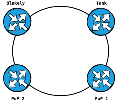
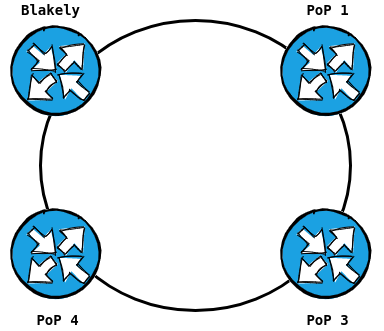
This ultimately collapses to make our core ring (with a shortcut path)
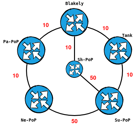
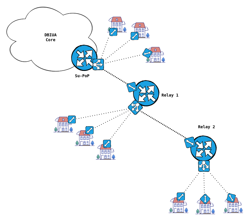
Connections to the members
Each PoP could have multiple relay sites daisy-chained below it. These points have no alternate paths, they are just means to reach members who are further away from one of our PoP's.
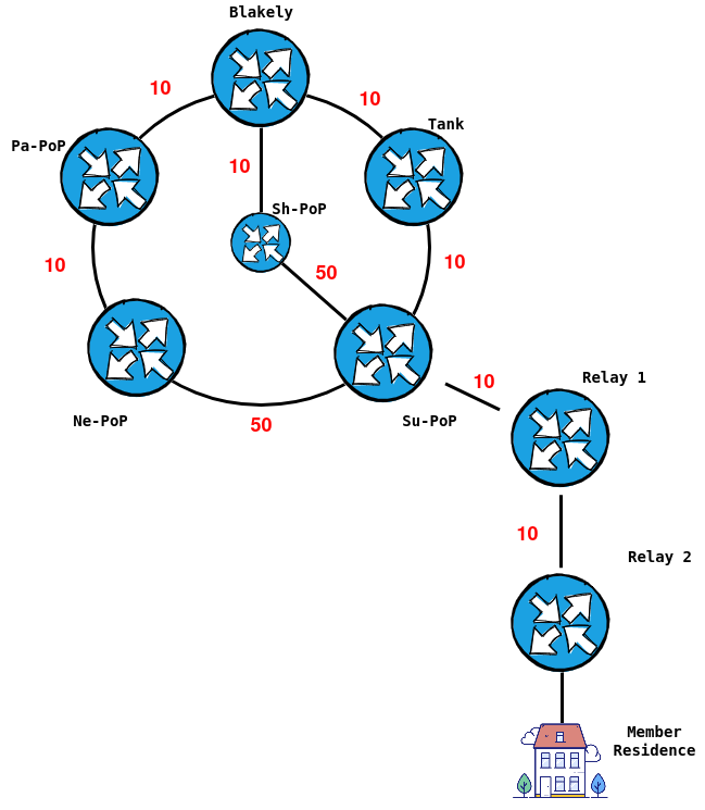
In the above diagram, if the connection between Su-PoP and the Watertank fails, there is an alternate path via Ne-PoP; However, if Relay 1 to Relay 2 fails, then everything south of Relay 2 is, unfortunately, down.
You have to imagine that off of every PoP, there is is at least one relay. Each relay has a PtMP radio that serves another relay, and potentially directly connected members.
What makes OSPF so dynamic?
All the time, OSPF routers are chatting. The two things they are sending are updates on the topology, and heartbeats – or keepalives – in the form of "Hello" packets.
Let's take a look:
root@wt-er:~# tcpdump -i eth0 host 224.0.0.5
tcpdump: verbose output suppressed, use -v or -vv for full protocol decode
listening on eth0, link-type EN10MB (Ethernet), capture size 262144 bytes
17:44:26.228788 IP 10.0.0.7 > ospf-all.mcast.net: OSPFv2, Hello, length 64
17:44:26.229488 IP 10.0.0.40 > ospf-all.mcast.net: OSPFv2, Hello, length 64
17:44:29.205888 IP 10.0.0.4 > ospf-all.mcast.net: OSPFv2, Hello, length 64
17:44:29.214227 IP 10.0.0.13 > ospf-all.mcast.net: OSPFv2, Hello, length 64
17:44:31.221995 IP 10.0.0.3 > ospf-all.mcast.net: OSPFv2, Hello, length 64
17:44:31.469316 IP 10.0.0.40 > ospf-all.mcast.net: OSPFv2, LS-Update, length 92
^C
6 packets captured
52 packets received by filter
4 packets dropped by kernel
root@wt-er:~#
From this packet capture, we can see that this router at our tank location is receiving multiple keepalives from it's peers (on a point-to-multipoint radio).
By default, for broadcast or Point-to-Point interfaces, the interval in which OSPF routers send these hellos is 10 seconds and it will declare the link dead if a hello is not received within 40 seconds
We can also see that it's sending these keepalives to the multicast address of 224.0.0.5 (All OSPF Routers). Yes, multicast transport is required for OSPF to work – unless you encapsulate it.
If you're not familiar with multicast, think of it this way. In the song "Hey Ya!", André 3000 yells "Okay now, ladies..." and the only the women respond, "Yeah?". Well, now imagine he yells out "Hello, OSPF routers [224.0.0.5]". The routers would know it is they that are being addressed.
Broadcasts, in the case of ARP, are more like yelling "HEY, EVERYBODY!" ... and continuing with, ".... I'm looking for 10.0.0.25". Everyone, except for .25, then realizes their attention wasn't actually needed and discards the message from their brains.
Continuing on, Let's take a closer look at a Hello packet:
root@wt-er:~# tcpdump -i eth0 host 224.0.0.5 -vv
tcpdump: listening on eth0, link-type EN10MB (Ethernet), capture size 262144 bytes
17:52:54.281058 IP (tos 0xc0, ttl 1, id 36, offset 0, flags [DF], proto OSPF (89), length 100)
    10.0.0.7 > ospf-all.mcast.net: OSPFv2, Hello, length 64
        Router-ID 172.x.x.15, Backbone Area, Authentication Type: MD5 (2)
        Key-ID: 1, Auth-Length: 16, Crypto Sequence Number: 0x0017be2c
        Options [External]
          Hello Timer 10s, Dead Timer 40s, Mask 255.255.255.0, Priority 1
          Designated Router 10.0.0.40, Backup Designated Router 10.0.0.13
          Neighbor List:
            172.x.x.1
            172.x.x.7
            172.x.x.3
            172.x.x.8
172.x.x.20The above Hello packet shows many things:
- A list of our neighbours' neighbours
- It's network mask
- What Auth type (MD5) and the Key-ID it matches (1)
- Which Area it's in (backbone / Area 0)
- It's router-ID (as we set in the config)
- Who it's Designated Router & Backup DR are (more on that later)
For OSPF routers to start exchanging prefixes, some things must match:
- Area ID
- Authentication (if enabled)
- Hello and Dead Intervals
- MTU Size
- Subnet mask (on broadcast interfaces only)
Redundancy
Redundancy comes into play when the primary path, calculated by lowest cost, fails. The OSPF router will wait until the dead timer expires and then re-calculate the best path it knows from the Link-State database.
We can see this below in the scenario where Mr. Tomato wants to send TPS reports to Mr. Skull Racer.
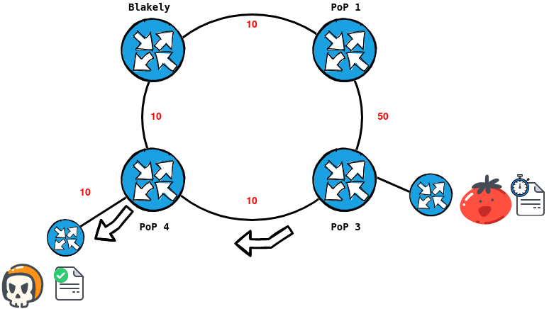
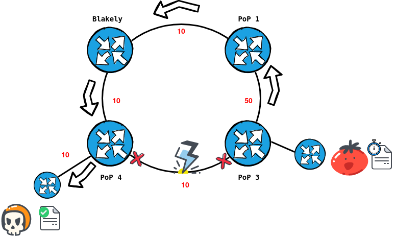
In the scenario, the link between PoP 3 and 4 is struck by lightning (very real possibility, considering we strap majority of our equipment to trees). PoP 3 waits up to 40 seconds to receive a hello packet from PoP 4, then it will declare the path dead and re-calculate to go via the "long-haul" path.
Beyond that, it will also do the neighbourly thing and update it's OSPF neighbours that it's "link state" has changed, thus causing a chain reaction in the Topology to re-calculate a new link-state topology.
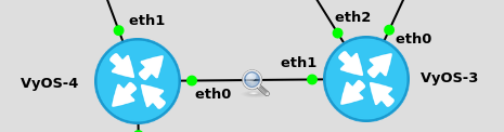
A magnifying glass view
To understand how the topology is built, we can look at what happens when a new router comes onto the network. To demonstrate this, I built the following mini lab topology:
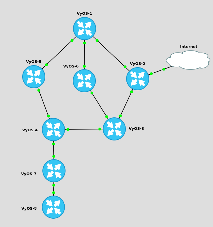
When an OSPF router first comes online, it must go through the various OSPF states to reach the "Full" state with it's neighbour.
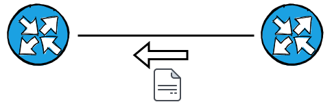
Once they have proved Bi-directional connectivity (both routers have seen the other routers hello packet), they will both offer a DB Description update.
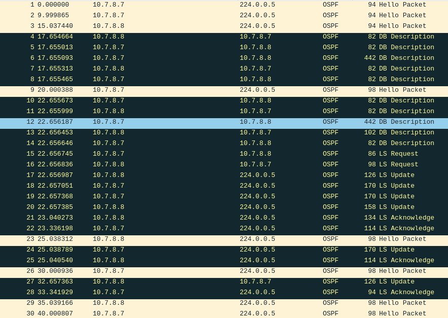
You can see in frame 6, that Router 7 has 442 bytes worth of information to inform Router 8 about. Here's what that consists of:
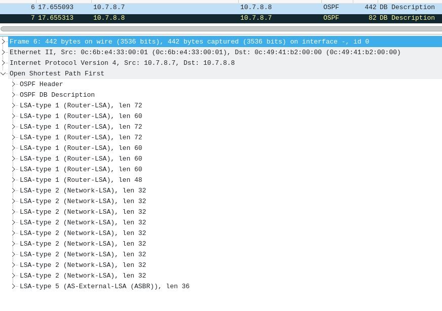
It's a list of all the Link-State Advertisements (LSAs) it has received. These LSAs were advertised by the routers in the topology.
For a closer look, we can see this on the router itself.
vyos@VyOS-7:~$ show ip ospf database

       OSPF Router with ID (172.16.1.7)

                Router Link States (Area 0.0.0.0)

Link ID         ADV Router      Age  Seq#       CkSum  Link count
172.16.1.1      172.16.1.1       813 0x8000000e 0x70d7 4
172.16.1.2      172.16.1.2       803 0x80000009 0x4b41 3
172.16.1.3      172.16.1.3       802 0x8000000d 0x677b 4
172.16.1.4      172.16.1.4       791 0x8000000c 0xae48 4
172.16.1.5      172.16.1.5       742 0x80000008 0xee7e 3
172.16.1.6      172.16.1.6       803 0x80000008 0x5edd 3
172.16.1.7      172.16.1.7       820 0x80000008 0x79ce 3
172.16.1.8      172.16.1.8       711 0x80000005 0xe4b3 2

                Net Link States (Area 0.0.0.0)

Link ID         ADV Router      Age  Seq#       CkSum
10.1.2.2        172.16.1.2       994 0x80000002 0xc249
10.1.5.5        172.16.1.5        22 0x80000002 0x9b64
10.1.6.6        172.16.1.6      1323 0x80000002 0x8e6d
10.2.3.3        172.16.1.3       572 0x80000002 0xb352
10.3.4.4        172.16.1.4       991 0x80000002 0xa45b
10.3.6.6        172.16.1.6       763 0x80000002 0x8a6d
10.4.5.5        172.16.1.5       952 0x80000002 0x9564
10.4.7.7        172.16.1.7       690 0x80000002 0x7b76
10.7.8.8        172.16.1.8        71 0x80000002 0x687f

                AS External Link States

Link ID         ADV Router      Age  Seq#       CkSum  Route
0.0.0.0         172.16.1.2       723 0x80000004 0x186e E1 0.0.0.0/0 [0x0]

vyos@VyOS-7:~$
You can see it contains details about the routers on the topology, and the numbers of links they are responsible for. It also contains the prefixes, both internal and external (the default route we injected via our configuration), along with their metrics (cost).
Let's look at a prefix more precisely:
vyos@VyOS-7:~$ show ip ospf database network 10.4.5.5

       OSPF Router with ID (172.16.1.7)

                Net Link States (Area 0.0.0.0)

  LS age: 1087
  Options: 0x2  : *|-|-|-|-|-|E|*
  LS Flags: 0x6
  LS Type: network-LSA
  Link State ID: 10.4.5.5 (address of Designated Router)
  Advertising Router: 172.16.1.5
  LS Seq Number: 80000002
  Checksum: 0x9564
  Length: 32
  Network Mask: /24
        Attached Router: 172.16.1.4
        Attached Router: 172.16.1.5

vyos@VyOS-7:~$
As the the prefix itself subtley hints, we can see this prefix is a /24 that lives between Router 4 & 5. Once router 8 received this in it's database, and determines it's the best path, it can then install it in it's Routing table and Forwarding table.
In the exchange, you can see there are also LS Requests and LS Updates. This is the routers comparing their databases and making sure that they have the most correct & true information. After an LS Update is sent by a neighbour, the other neighbour will send back an LS Acknowledge, like an Ack to a Syn in TCP.
Periodically, on your topology, you will see LS Updates flood. Don't worry, as this is just neighbourly routers advising their neighbours what the current status of their links are.
Topology Changes
Finally, let's look at a topology change. To simulate a link loss, like in the skull & tomato link failure, I will shutdown the link between router 7 & 8. This will isolate router 8 from the network
vyos@VyOS-7:~$ show interfaces | match /24
eth0 10.4.7.7/24 u/u
eth1 10.7.8.7/24 u/u
vyos@VyOS-7:~$ configure
[edit]
vyos@VyOS-7# set interfaces ethernet eth1 disable
[edit]
vyos@VyOS-7# show | compare
[edit interfaces ethernet eth1]
+disable
[edit]
vyos@VyOS-7# commit;save;exit
Saving configuration to '/config/config.boot'...
Done
exit
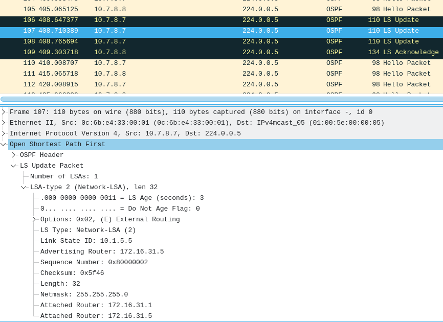
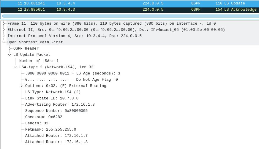
vyos@VyOS-7:~$ Now let's see what a packet capture between router 3 & router 4 looks like:
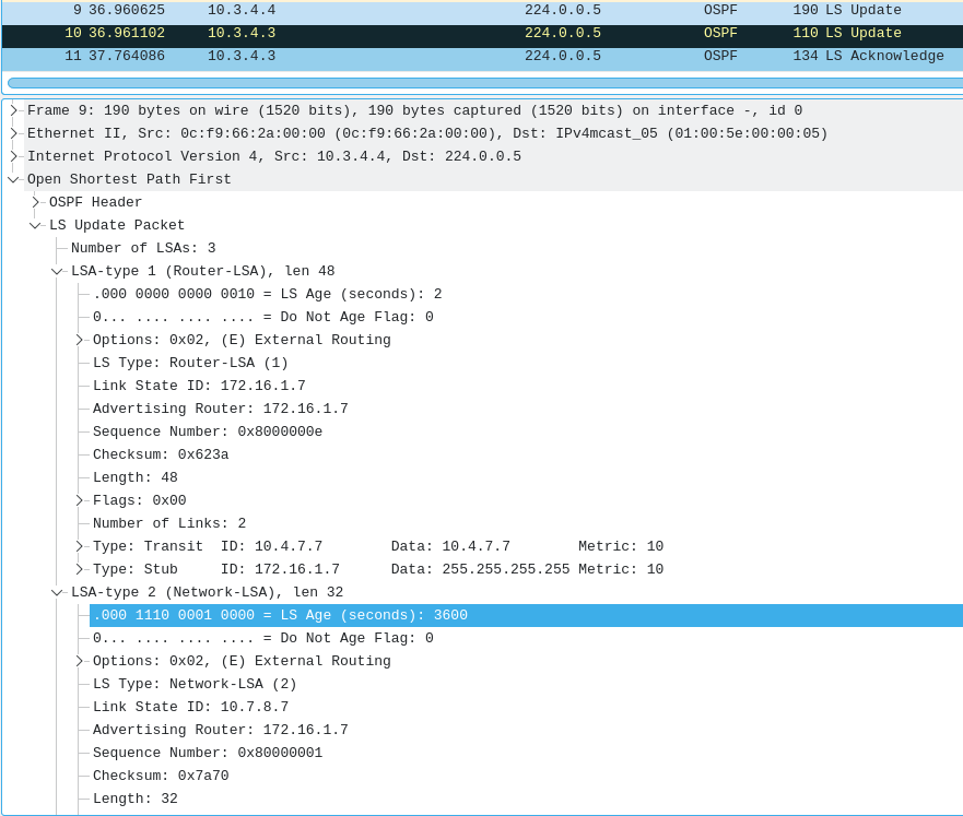
Router 4, who receives the update first, floods it to it's neighbours, including Router 3. This LS update states It has two updates for a Router-LSA & it's Network LSA. It now is responsible for links 10.4.7.7 & 172.16.1.7 (note: 10.7.8.7 is absent).
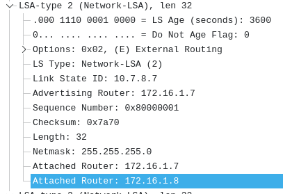
Also, note the LS Age on the LSAs. For the Router-LSA, it's LS age is 2 seconds, which is good. For the Network LSA of 10.7.8.7, it's LS Age is 3600 seconds, which is the maximum. This effectively tells the routers to delete this from their routing table.
Since Router 7 was the only viable way to reach this prefix from the topology, this route will effectively disappear. As will 172.16.1.8's prefix, as it was only listed as an attached router on this Network-LSA.
Now, let's restore the link and see what happens
vyos@VyOS-7:~$ configure
[edit]
vyos@VyOS-7# delete interfaces ethernet eth1 disable
[edit]
vyos@VyOS-7# show | compare
[edit interfaces ethernet eth1]
-disable
[edit]
vyos@VyOS-7# commit;save;exit
Saving configuration to '/config/config.boot'...
Done
exit
vyos@VyOS-7:~$ 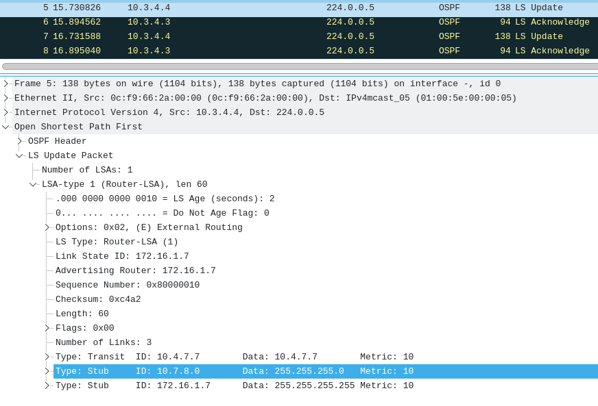
Router 4 then receives & floods an LS-Update from Router 7. This LS-Update advises that Router 7 now has link-state that includes 10.7.8.0/24 being reachable.
We'll also receive the LSA's from router 8, informing us that this prefix is just fine and we can continue to route to it, restoring connections for our members downstream of router 7
If there is a way, OSPF will find it
Point-To-Multipoint Considerations
The last thing I'd like to mention is considerations of bandwidth and flows for PtMP links. When you consider the chatty nature of OSPF (Hellos, Flooding updates, etc.), there's a lot going on all the time.
When you imagine a broadcast domain that is setup on a PtMP radio, there could be a lot of routers connected. If each router needs to maintain a full adjancency, there's a lot of synchronization to be done.
This could cause bandwidth & packet/frame processing to grow exponentially, when there are more important packets to be pushed like Zoom packets.
To solve this, OSPF has a process called the Designated Router (DR) Election. This process essentially elects two routers to be responsible for performing the Sychronization of the Link-State DB with neigbours, drastically cutting down on noise.
In our Tank example, as we saw in our first tcpdump, there are a fair amount of routers on this segment.
me@wt-er:~$ show ip ospf neighbor | match "Neig|eth0"
Neighbor ID     Pri   State            Dead Time   Address         Interface           Instance ID
172.x.x.7       1   2-Way/DROther    00:00:31    10.0.0.3        eth0                    0
172.x.x.3       1   2-Way/DROther    00:00:29    10.0.0.4        eth0                    0
172.x.x.15      1   2-Way/DROther    00:00:34    10.0.0.7        eth0                    0
172.x.x.8       1   Full/Backup      00:00:30    10.0.0.13       eth0                    0
172.x.x.20      1   Full/DR          00:00:33    10.0.0.40       eth0                    0
me@wt-er:~$
By default, OSPF will select the router with the highest priority (you can manually configure this) as the DR and the second highest as the Backup DR (BDR). If all priorities are equal, it will then look for the highest router-id.
In the above output, .20 is selected as the DR because it has the highest Loopback / Router-ID. Router 15 would typically be the BDR, but it may have not been online / reachable, at the time of DR election. If the DR election were to be done again, it would likely become the BDR.
You'll also notice that the other routers do not form a Full adjacency. They stay in the "2-way" state. Do not be alarmed when you see this. This is because they have two-way connectivity, as proven by their hellos, but they do not Exchange DBDs or LSAs.
Now consider the placement of your Designated router; If your PtMP radio has low bandwidth capability, you might want to be weary of where your DR is placed.
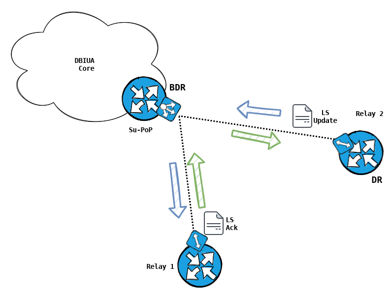
In my mock example above, Su-PoP has two relays connected on a PtMP radio. Relay 2 was selected as the DR (this would not be abnormal, as our router-id increments as we onboard routers farther down the chain).
As it's role entails, the DR must keep it's neighbours informed on the state of the Link-State topology. However, if it is doing so with Relay 1, which is also a PtMP spoke, traffic doubles as it hairpins through the radio at the PoP. This would make the 442 bytes we saw in a previous capture double to to 884 bytes as it hairpins through the radio (442 bytes in, and 442 bytes out).
This could be problematic, if you have an oversubscribed or low bandwidth capability radio, such as a 900Mhz radio.
This is also something to consider, should a user behind Relay 1 need to communicate directly with a user behind Relay 2. In this scenario, you might want to consider deploying dedicated radios between the PoP & these relay sites, allowing the router to handle the traffic with dedicated bandwidth, per link.
Conclusion
I will say that I am fairly happy with the state of the routing. Things go down, things come back up; OSPF finds a way. It's also relatively easy to on-board new sites and members, especially after some of the design optimizations Chris has made for the topology.
We get a lot of emails and inquiries from various people around the world, trying to replicate our setup. I hope this post answers most of your questions. I hope the hyperlinks I included expand on your knowledge even further. If not, please do reach out and I will be happy to elaborate.
If I could offer one piece of advice, It would be to keep it super simple (KISS model); Allow your configuration to be be greater for the sum of it's parts.